
Stepping into the World of Fluid Dynamics
The most challenging class from my university days was a grad-level course on thermal convection. For four months, our professor rederived our favorite fluid mechanics equations using partial differential equations. (I scraped by with a C+ and learned just enough about Navier-Stokes equations to sound pretentious.)
As complex as the math was, the takeaways were simple: Air is a fluid, fluids are complicated, and if you can’t measure a fluid, then you can’t control it. This lesson is true for all fluid mechanics and is certainly true for air distribution. To have proper air distribution in a space, we must be able to measure the airflow rate with reasonable accuracy.
Types of Flow Measurement Devices
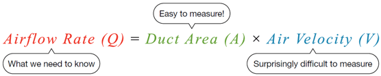
In its simplest form, volumetric flow rate can be measured as the product of air velocity and duct area. With the regrettable target word count for this blog post, we will omit corrections for elevation and density (my thermal convection professor would throw a fit). Duct area is always constant and simple to measure using geometry (A = πr2 for a round duct). The real linchpin of this measurement is the air velocity.
Many instruments exist that measure duct air velocity through varying methods. Balancing contractors use pitot tubes and flow hoods; handheld sensors utilize hot-wire and vane anemometers; and higher-end systems use orifice plates and venturis to measure flow rate based on pressure differentials across a fixed geometry. However, for commercial HVAC systems and particularly in terminal units, we most often use cross-flow sensors.
All Price terminal units use a SP300 Cross-Flow Sensor, first patented by Price, to measure the airflow rate in their primary air inlets. This airflow measurement is used as feedback to control the airflow damper and is readable on the thermostat and building automation system (BAS) for the facility. Cross-flow sensors are ideal because they are robust, economical and accurate enough for HVAC controls (typically ± 5%, but sometimes better).
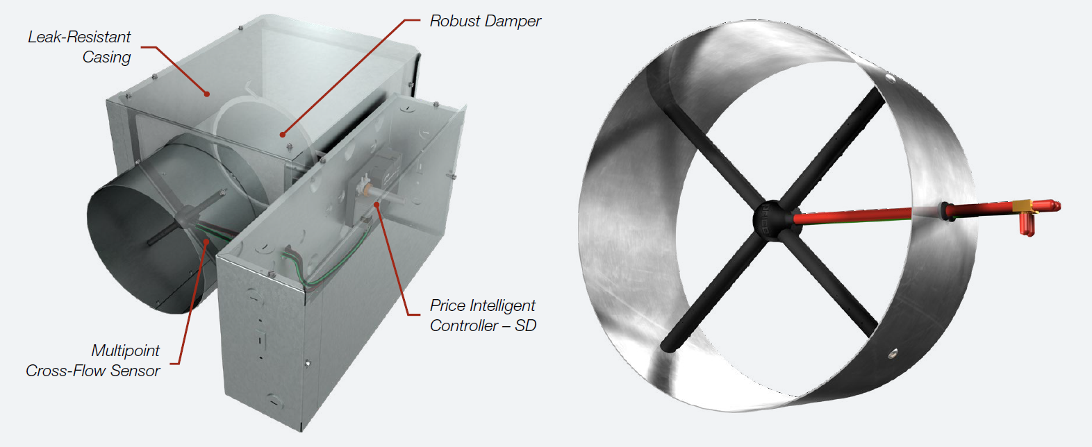 |
| Anatomy of a Price Single-Duct Terminal Unit (left); the controller uses the flow measurement from the SP300 Cross-Flow Sensor (right) as feedback and adjusts the damper blade accordingly |
How Does the Cross-Flow Sensor Physically Measure the Airflow?
The movement of air through ductwork is fully dependent on the duct pressure. Applying Bernoulli’s principle, air pressure has both a stationary component, called static pressure (think a balloon), and a moving component, called velocity pressure (think a gust of wind). In ductwork, there is always a combination of both static pressure and velocity pressure. The pressure exerted by moving air is the sum of these pressures, called total pressure. The SP300 does not directly measure air velocity or flow rate; rather, it measures the average differential between total pressure and static pressure in the primary air duct:
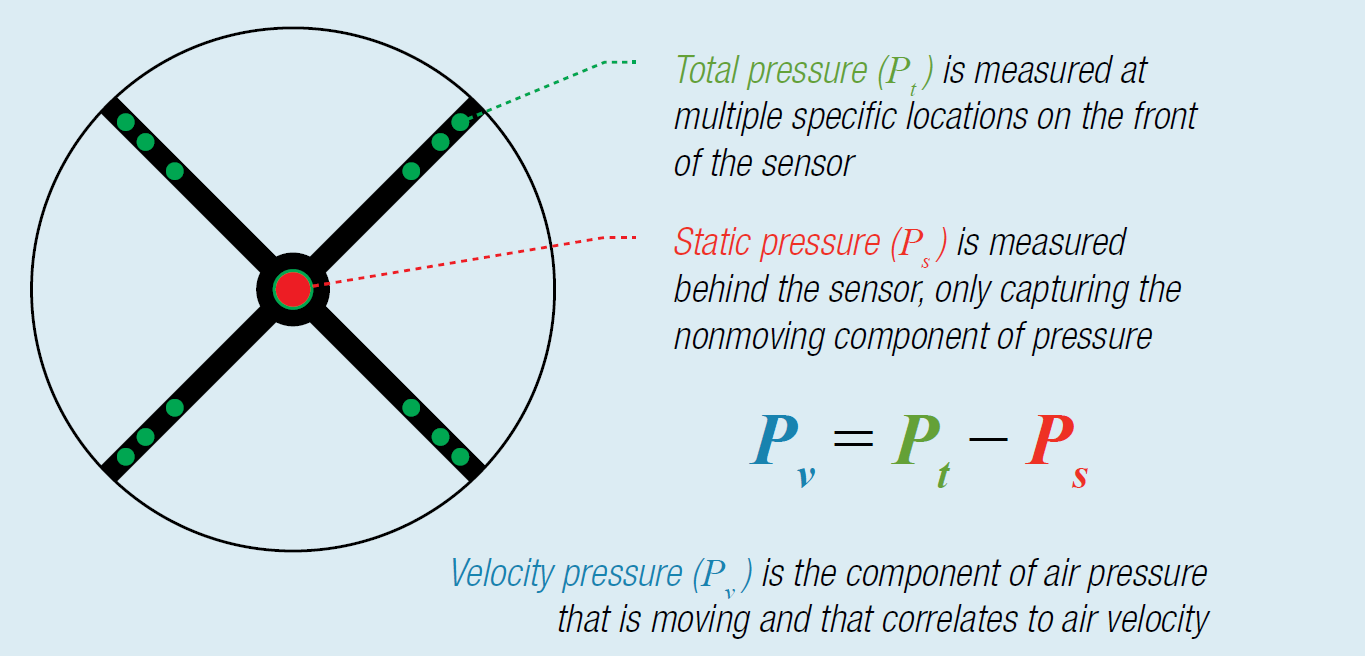
The multiple total pressure ports are important. Air velocity is rarely uniform across a duct, and the 12 pressure ports help gather an average total pressure across the face, similar to the duct traverses performed by air balancers. Multiple ports also help with pressure amplification, leading to a smaller absolute minimum measurement.
The velocity pressure, Pv, measurement can be equated to air velocity using the following equation (where V is air velocity and ρ is air density):
 Going back to our original equation, we can then measure the airflow rate, Q, with this equation (where A is duct cross-sectional area):
 If we assume standard air density (close enough) and a constant duct geometry (which better be constant), we can simplify this equation to the following (where K is the amplification factor):
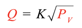
The K-factor is unique to each size of terminal unit and includes all the values for duct area and air density, as well as some calibrated corrections due to the geometry of the flow sensor itself.
Can We Put Units on These Measurements?
In the US HVAC market, pressure is measured in units of inches water gauge (in.w.g.), where 1 in.w.g. is literally the pressure exerted by a column of water 1 inch tall.
When you do the math, 1 in.w.g. of velocity pressure equals approximately 4,000 feet per minute (fpm) of air velocity. This is very high for ductwork, and your air distribution system will be very noisy at this air velocity. Conversely, a duct velocity of 400 fpm is only 0.01 in.w.g., which is exceedingly low and imperceptible to most pressure sensors.
So How Does This Affect Terminal Units?
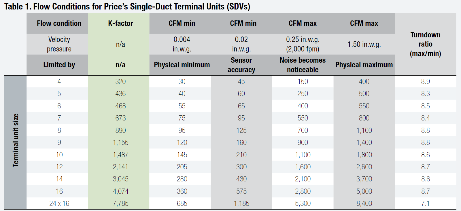
In general, the minimum design velocity pressure should not dip below 0.02 in.w.g. The accuracy of most commercial pressure sensors drops off below this limit. While some terminal unit controllers can read pressure signals as low as 0.004 in.w.g., there are additional considerations for the system calibration required to achieve consistent airflow measurement at that level.
The maximum design air velocity entering a terminal unit should not typically exceed 2,000 fpm (or 0.25 in.w.g. velocity pressure). The generated noise becomes noticeable above this, though pressure sensors can physically measure up to a maximum of 1.5 in.w.g. velocity pressure.
The ratio between the minimum and maximum flow of a terminal unit is known as the turndown ratio. Larger turndown ratios allow for greater flexibility in the controls of a given terminal unit.
Putting all of this information together, we can determine the minimum flows, maximum flows and turndown ratios of all our single-duct terminal units, as seen in table 1.
For the engineers who want to learn more about fluid mechanics (I know you exist), additional recommended readings include the following:
- Price Engineer’s HVAC Handbook (Edition 2): Chapter 2, “Fluid Mechanics”
- 2025 ASHRAE Handbook – Fundamentals: Chapter 3, “Fluid Flow”
- Your local fluid mechanics textbook
If this topic piques your interest or if you have questions, reach out to our Air Moving team at airmovement@priceindustries.com.
 |
Ryan Johnson is Manager of Engineering Programs for Price's Innovation and Learning team. He is based out of Price's facility in Suwanee, GA. |