
Cool Tips and Hot Takes for Air Distribution Design
At Price, we pride ourselves on our contributions to The Science of Comfort™ (we have the phrase trademarked, after all). If you’re a regular reader of the blog, you’ll understand the rigorous testing and research behind all the air distribution solutions we manufacture. Our team at Price Research Center North (PRCN) in Winnipeg, MB, is accustomed to maintaining the highest test standards and methodologies behind the data published in our catalog.
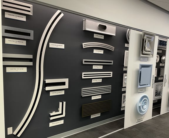 |
| The GRD wall at Price Technical Center West in Casa Grande, AZ |
The challenge for engineers is understanding when standardized tests may not align with their real-life applications. Good engineers can identify their unique design limitations and anticipate how they will affect the performance of their air distribution system. Over the years, our application engineering teams have encountered many such recurring challenges in the field. This post offers lessons we’ve learned for grilles, registers and diffusers (GRDs) in particular.
Lesson 1. Duct Inlets Matter
All GRDs are tested with a little-known method called ASHRAE Standard 70-2023, Method of Testing the Performance of Air Outlets and Air Inlets. Among the standard’s many requirements is that GRDs are to be tested with an ideal inlet duct connection. This is achieved with the equivalent of at least three duct diameters of rigid, straight duct above the diffuser.1 It is, however, highly unlikely that a contractor will have this much space to work with in the field. Substituting a rigid elbow or flexible elbow onto a GRD is typical, but these can result in increased noise generation and flow asymmetry.
Internal testing at Price’s mock-up facility in Suwanee, GA, resulted in the effects on throw, noise and pressure drop based on inlet conditions shown in the table below.
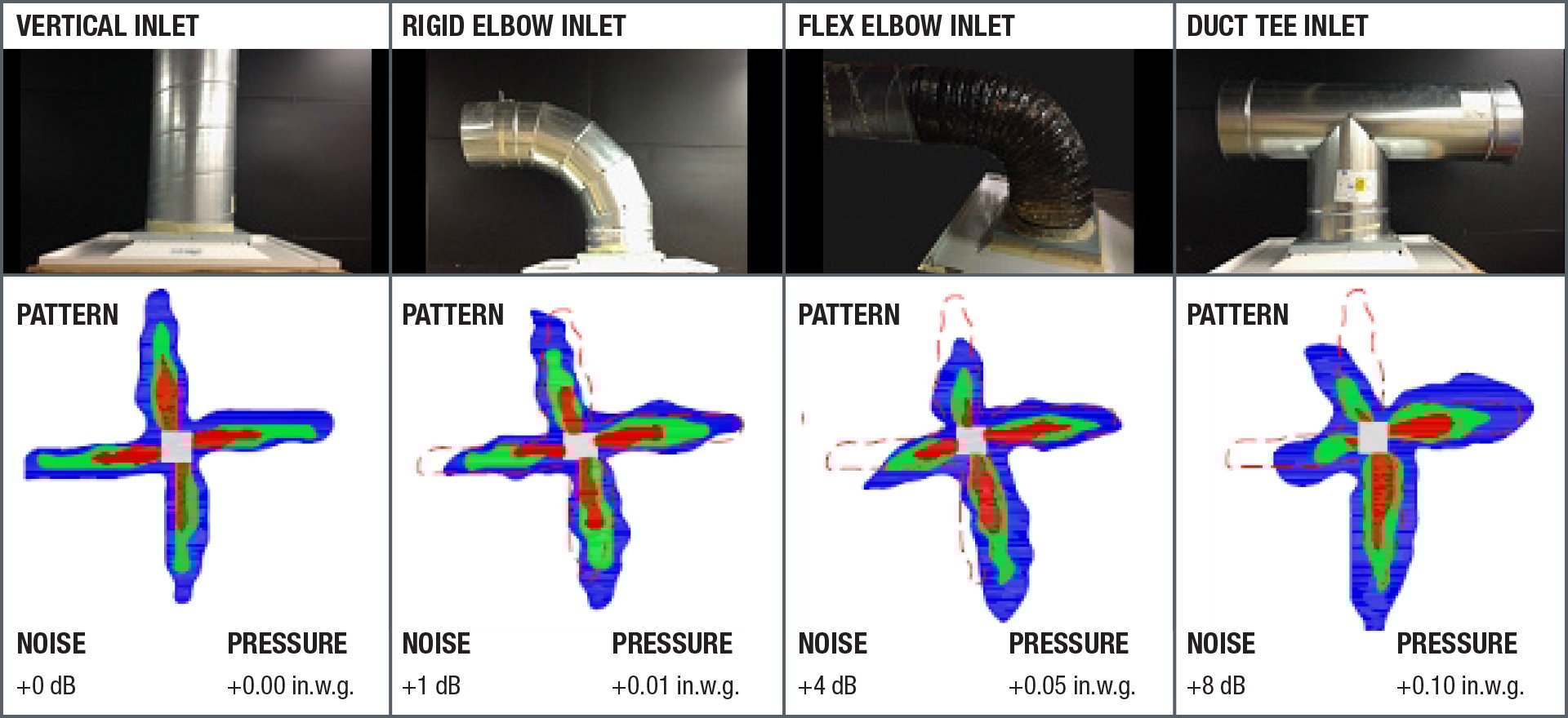 |
| Inlet effects on a 12 by 12 in. Modular Louvered-Face Diffuser (SMD) at 500 fpm neck velocity |
|
Pro Tip: Maintain a minimum of 8 in. of straight, rigid duct connection behind GRDs to keep closer to catalog performance. More length is better. |
Lesson 2. In-Neck Balancing Dampers Add Noise
In-neck balancing dampers such as the VCR7, VCR8 and VCR9 are installed on the necks of diffusers to balance their pressure drop relative to other diffusers on a duct run. Ideally, balancing dampers should be installed farther upstream in the ductwork, but in cases where the duct is not accessible, an in-neck damper is a practical option.
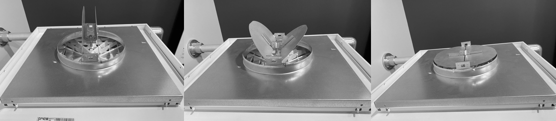 |
| A diffuser with a Volume Control Damper (VCR8) set to 100% open (left), 50% open (center) and 0% open (right) |
Unfortunately, dampers act as obstructions to the airflow and are thus inherently noise generators. The greater the pressure across the damper, the greater the noise. A larger duct system requiring many balancing dampers in mostly closed positions will produce more pressure buildup in a system and, consequently, more noise.
|
Pro Tip: When using in-neck balancing dampers, anticipate at least +3 dB noise generation at the diffuser. Generated noise can increase by more than 10 dB as velocity increases and/or damper position closes.2 |
Lesson 3. Spiral Duct Grilles Have a Speed Limit!
Spiral duct grilles are a common choice for distributing air from a central spiral duct branch, especially with the popularization of industrial-style open ceilings in today’s commercial spaces. However, here’s a fun fact: Spiral duct grilles are tested per ASHRAE Standard 70, but the method of test does not currently reflect how these grilles are installed and operated in the field, with discharge perpendicular to the airflow within the duct.
Don’t worry – we’ve investigated this! Initial testing at PRCN has demonstrated that to get optimal performance from spiral duct grilles, it is best to keep the duct velocity at a minimum. As the duct velocity increases, the amount of air escaping the spiral duct grille begins to drop off. At much higher duct velocities, it is possible for room air to be sucked into the duct itself – the opposite of what we want our ventilation system to do!
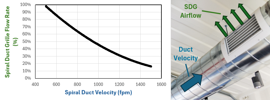 |
| The reduction in supply airflow through a Price Extruded Aluminum Supply Spiral Duct Grille (SDGE) as duct velocity increases; data is for a 12 by 6 in. SDGE on a 12 in. diameter duct at 0.2 in.w.g. static pressure |
One common solution to this problem is to install an “air scoop” behind the spiral duct grille to capture the incoming air. Evidence suggests these do in fact regulate the airflow, though care should be taken to not let duct velocity get too high or you risk excess noise generation. Opposed-blade dampers are sometimes installed behind spiral duct grilles too, but these tend to exacerbate the problems listed above, inducing more air into the duct at higher velocities and increasing the spiral duct grille’s generated noise.
|
Pro Tip: For spiral duct grilles, keep the duct velocity below 1,000 fpm to maintain air distribution. Lower is better. |
Where Do I Learn More?
We are glad you are curious! Here are a few resources to guide you on your air distribution journey:
- Price Engineer’s HVAC Handbook (Edition 2): Chapter 9, “Mixed Air Distribution,” and Chapter 15, “Displacement Ventilation,” are must-reads.
- Price Learning Portal (PLP): This online learning hub includes webinars, white papers and quizzes that you can use to earn PDH credits.
And of course, you can reach out to us at GRD@priceindustries.com to talk to application engineers who deal with room air movement every day.
References
- American Society of Heating, Refrigeration and Air-Conditioning Engineers (ASHRAE), ASHRAE Standard 70-2023: Method of Testing the Performance of Air Outlets and Air Inlets (2023).
- ASHRAE RP-1335: Effects of Typical Inlet Conditions on Air Outlet Performance (research project, University of Nevada, Las Vegas, 2011).
 |
Ryan Johnson is Manager of Engineering Programs for Price's Innovation and Learning team. He is based out of Price's facility in Suwanee, GA. |