
Best Practices for a Successful Mechanical System Design
Understanding how much space a fan coil unit needs is imperative for mechanical system design. Incorrect assumptions can create deviations between contract documents and finished buildings, which can lead to change orders and increased project costs for building owners. The type of fan coil unit, the options it is configured with and the overall design of the building’s HVAC system all influence the final installation requirements.
Understanding Fan Coil Equipment Dimensions
Equipment dimensions can be highly variable depending on the manufacturer, fan coil type and product configuration. Best practice is to use the manufacturer’s Revit families to ensure that the dimensions are correctly accounted for. Alternatively, the manufacturer’s submittals can be referenced for the generation of CAD blocks or Revit families by the mechanical consultant.
 |
 |
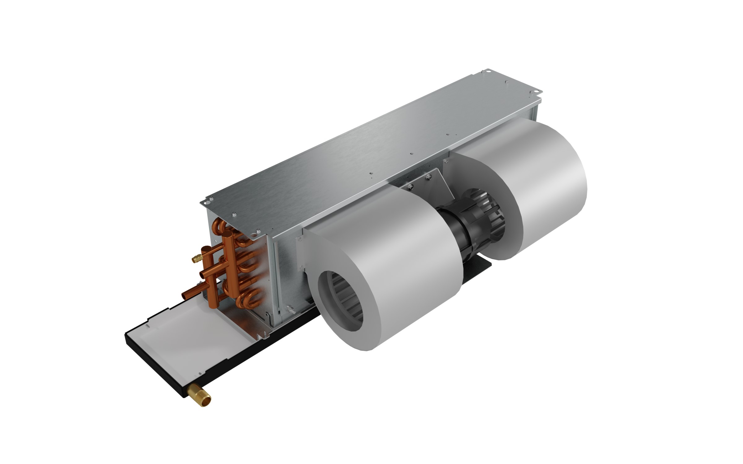
| Fan coils come in different configurations, such as Price's FCHC (left), which is a free-return horizontal fan coil, or Price's FCHP (right), which has a return air plenum enclosing the fan and motor assembly | |
For example, the Price Horizontal Low-Profile Fan Coil (FCH) web page includes free downloadable Revit families and product submittals. Additionally, many manufacturers have Revit plug-ins – such as the Price Revit Toolkit – that make it easy for users to access Revit families.
Leaving Space for Duct and Pipe Clearance
Fan coils connect to a combination of chilled water pipes, hot water pipes, supply ducts and return ducts. Early in the design development, it’s best practice to leave at least 1 ft. of clearance for duct connections and 6 in. of clearance for pipe connections. Consider leaving additional space for valves, strainers and pipe insulation depending on the intended application.
It is also critical to leave space for a condensate drain line. Assume ⅛ to ¼ in. per foot of pipe length and consult the local authority having jurisdiction for code requirements.
Considering Service Access
Fan coils require service access to maintain the motor/blower assembly, to clean heating and cooling coils, and to replace filters. Additionally, code-required clearance must be maintained for safe commissioning, testing and balancing, and maintenance of the electrical enclosure. The US National Electrical Code (NEC) requires 3 to 4 ft. of clearance from electrical enclosures.
NEC Clearance Recommendation
| Working Space | Voltage-to-Ground | |
| 0–150 V | 151–600 V | |
| Condition 1: Exposed live parts on one side of the working space and no live or grounded parts, including concrete, brick or tile walls and are on the other side of the working space | 3 ft. | 3 ft. |
| Condition 2: Exposed live parts on one side of the working space and grounded parts, including concrete, brick or tile walls and are on the other side of the working space | 3 ft. | 3.5 ft. |
| Condition 3: Exposed live parts on both sides of the working space | 3 ft. | 4 ft. |
Because of the variety of service access constraints, it is ideal to reference the manufacturer’s documentation, such as Price’s Fan and Blower Coil Service Access Clearance manual, to ensure your design leaves enough space.
Price’s project and application engineers are ready to assist design engineers, building owners, architects and mechanical contractors with product choices that can optimize air distribution system efficiency.
Click here to find a sales representative or technical expert near you, or reach out to our team at airmovement@priceindustries.com.
 |
Mark Mahon is Business Development Manager for Fan Coils and Terminals for Price's Air Moving team. He is based out of Price's Progress facility in Lawrenceville, GA. Click here to connect with him on LinkedIn. |