
In duct design and installation, system effect is the generation of higher than expected pressure drops through changes in duct direction or geometry. It can also be caused by improper installation of fittings, which result in excessive, unanticipated turbulence in the airflow. In short, system effect is the installed pressure drop which is different from the design pressure drop.
System effect typically refers to fan installations, but can also be determined for silencers and any geometry or directional change with non-ideal inlet or outlet conditions. Components that commonly experience system effect include duct take-offs, terminal units, chilled beams, diffusers, silencers, fans, and water coils.
Symptoms of system effect include excess static pressure drop, instability in air volumes through a device, excessive power consumption in a blower, lower fan air volumes, and higher levels of radiated and discharge sound.
Duct designers layout their ductwork in a way that minimizes the potential for system effect. However, as is often the case, the real world interferes. Obstructions such as fire suppression piping and electrical conduits can prevent the duct from being installed as drawn. As a result, additional fittings such as elbows may be installed without the length of inlet or discharge duct to allow the air velocity to be equalized.
When air experiences a change in direction, the air velocity profile in an elbow will shift (Figure 1). If another fitting is attached to the discharge of that elbow, the air velocity profile will not be fully formed. This will result in a higher pressure drop. To minimize this effect, turning vanes – as well as a length of straight ductwork – are often used to settle the air into a more ideal air velocity pattern.
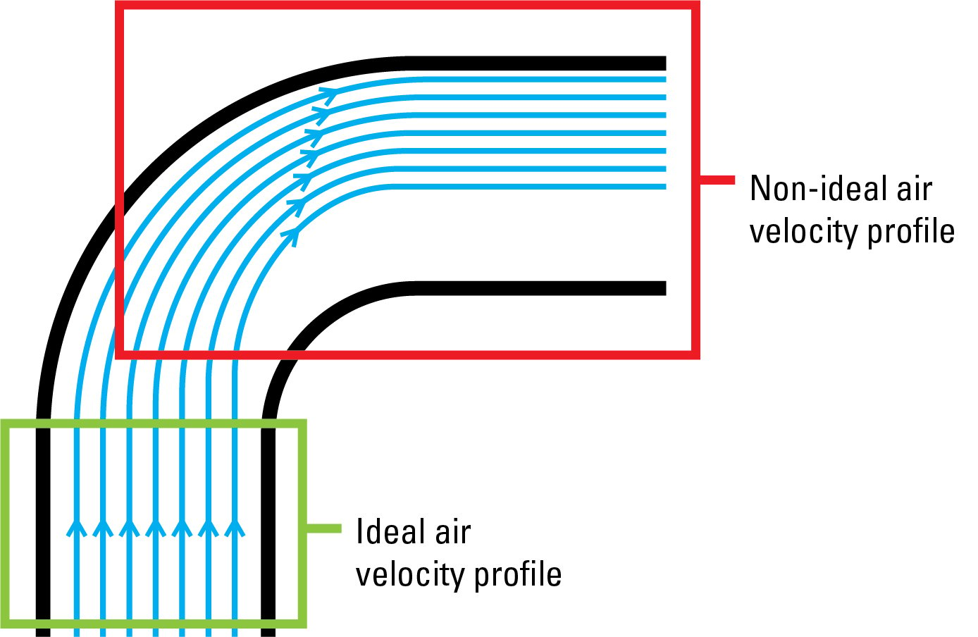
Figure 1: Ideal and non-ideal air velocity profiles in ductwork.
A typical recommended minimum length of straight ductwork is three equivalent diameters. Depending upon the velocity in the duct, the length of straight ductwork may be longer. A great way to see the impact of system effect is to look at silencers, as the inlet and discharge conditions can have a significant impact in sound absorption.
A silencer should be tested to the ASTM Standard E477-13e1, which states that there shall be straight duct of no less than five equivalent duct diameters upstream of the silencer, and not less than ten duct diameters downstream of the silencer. In “real-life” applications these conditions are rarely possible, but three to four duct diameters on both sides of the silencer should be a minimum design goal.
Diffusers and terminals can also be impacted by system effect. This results in higher sound levels and poor inlet discharge air patterns. Figure 2 shows the air velocity patterns in a diffuser with varying air inlet conditions.
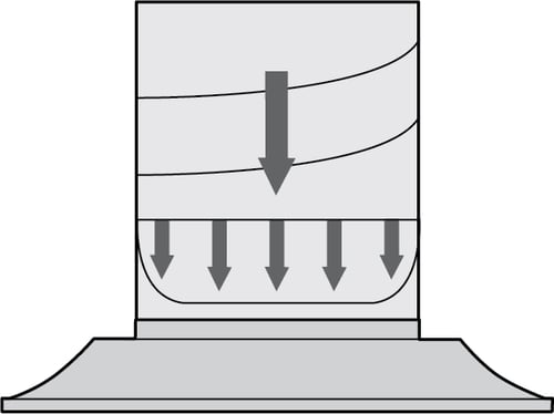
Basis of manufacturer's rating
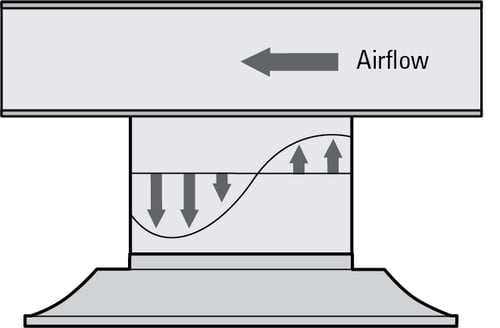
Sound levels up to 12 dB higher with no equalizing grid
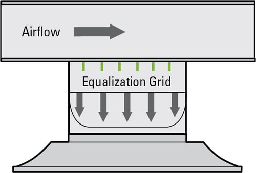
Sound levels same as manufacturer's rating with equalizing grid
Figure 2: Various inlet conditions for a diffuser
When a designer uses acoustic data for a terminal that was tested according to ASHRAE Standard 130, and then adds a silencer that was tested according to ASTM E477, the results will not be what the math would suggest. This is because the inlet and discharge ductwork lengths are now different than what was tested. Figure 3 shows the predicted NC value of the installation is 24, while the actual NC value is 35. When attaching silencers to terminals it is best to use units that are designed and tested as an assembly, such as the Price SDVQ.
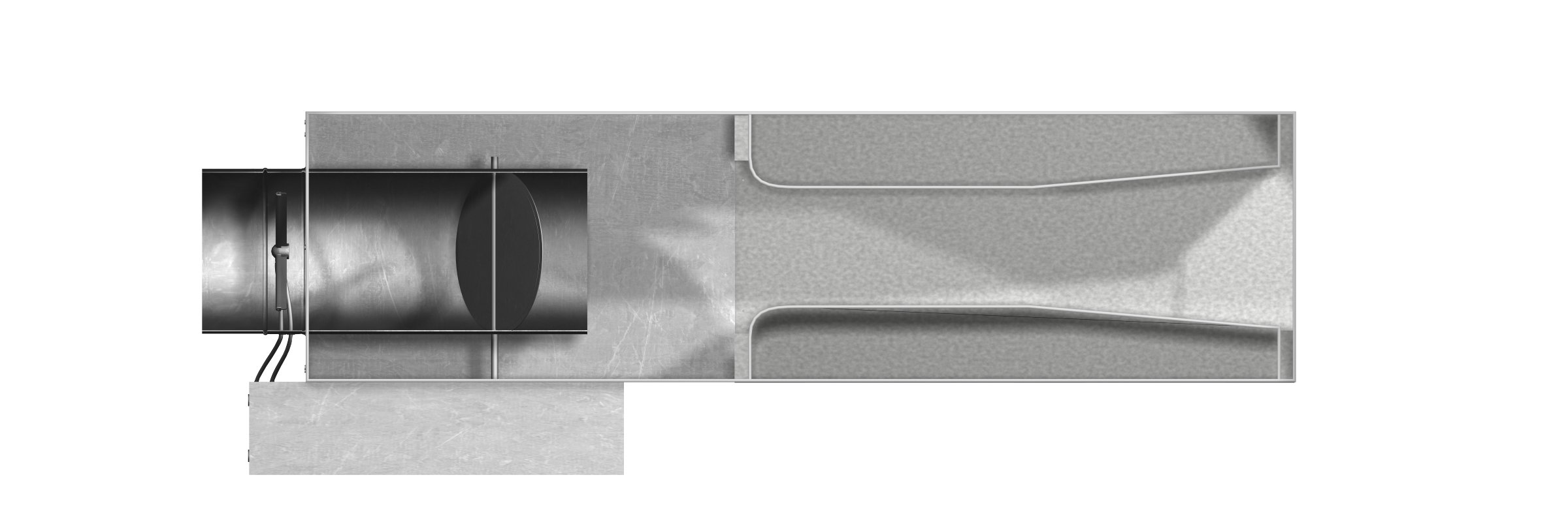
Figure 3: SDV (ASHRAE 130) + Silencer (ASTM E477) can be unpredictable
One thing to keep in mind is that static pressure drop is related to noise generation. The higher the turbulence due to pressure drop, the higher the noise generation.
For more information on this topic, the Price Engineering Handbook has several chapters that are relevant:
- Chapter 8: Duct Design
- Chapter 9: Mixing Ventilation
- Chapter 10: Noise Control
- Chapter 12: Terminals
- Chapter 13: Fan Coils and Blower Coils