Inlet Effects
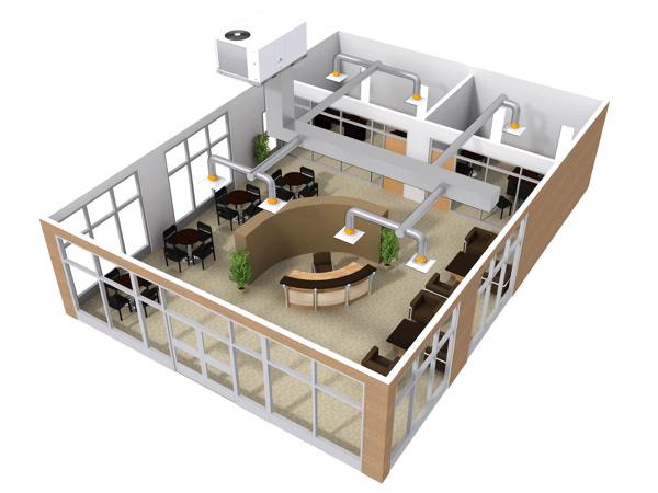
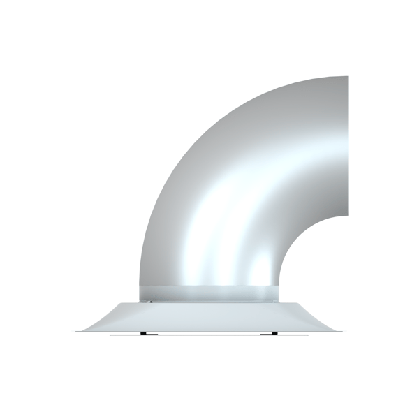
- Hard 90 Degree Elbow
- 90 Degree Flexible Duct Elbow
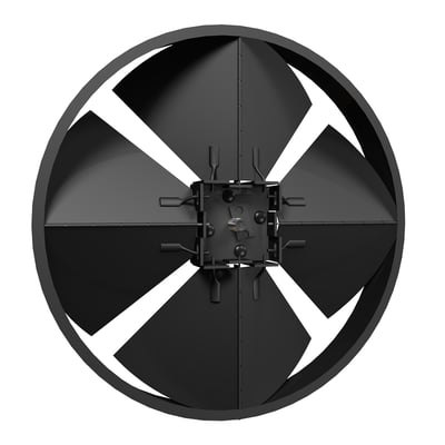
- Radial Opposed Blade Damper
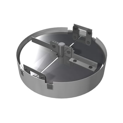
- Butterfly Damper
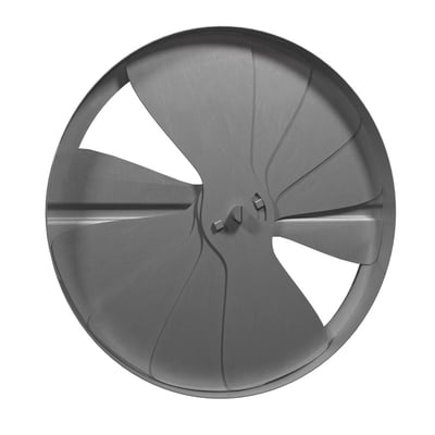
- Radial Damper
- Perforated diffuser
- Directional diffuser
- Radial diffuser
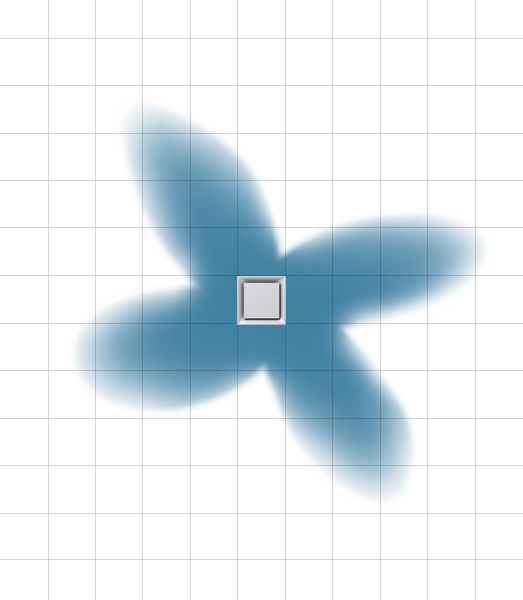
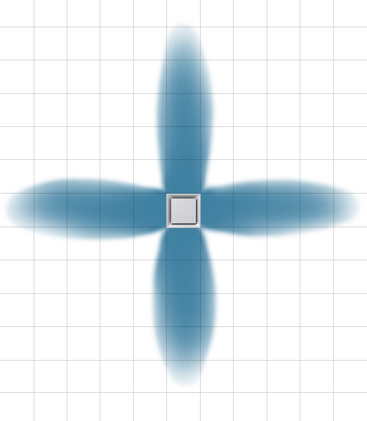
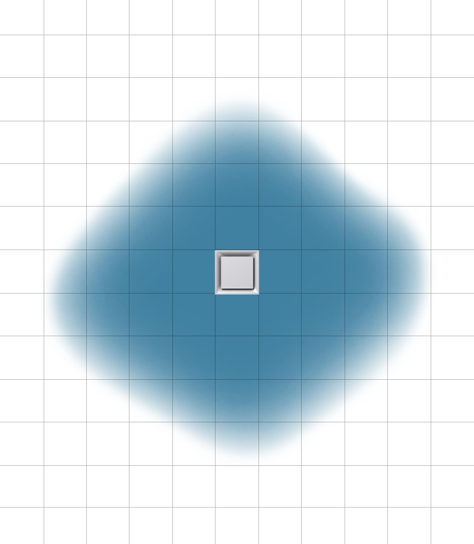
To illustrate the air pattern, constant velocity plots (isovels) that display an envelope of air at an equal velocity will be used. Note that the diffuser shown in each image is a generic image intended to represent the diffuser described in the text.
ASHRAE 70 Standard Installation Using Three Straight Duct Diameters
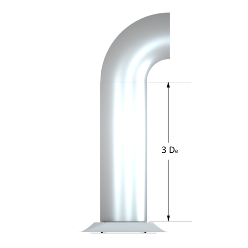
Figure 1: ASHRAE Standard 70 requires three duct diameters
Figure 2: Perforated Diffuser
Figure 3 displays the pattern delivered from a directional diffuser, like the Price SMD diffuser. This diffuser also displays four distinct air jets however, the airstreams root from the sides of the diffuser face instead of the corners, as was seen with the perforated diffuser.
Figure 3: Directional Diffuser
Figure 4 shows the air pattern from a radial patterned diffuser like the Price square plaque diffuser, model SPD. Unlike the first two diffusers, this product has a radial pattern encompassing a full 360 degrees surrounding the diffuser. As a result, the throw distances will be slightly shorter at the same airflows when compared to a four-way diffuser like the PDS or SMD.
Figure 4: Square Plaque Diffuser
90 Degree Hard Elbow
The first field installed inlet condition that will be discussed is a 90 degree hard duct elbow, the installation of which is shown in Figure 5. The diagrams below display two different isovels superimposed on top of each other.Figure 5: Hard Ducted Elbow Installation
The blue isovel represents ideal inlet conditions and will be included for comparison against all field installations. The purple isovel illustrates how the 90 degree hard elbow on the diffuser inlet affects the air pattern for the three different diffusers. The air pattern of the perforated diffuser is not significantly affected, as it still displays a distinct four-way throw shown in Figure 6. However it is clear that the 90 degree elbow has shifted the pattern slightly clockwise.
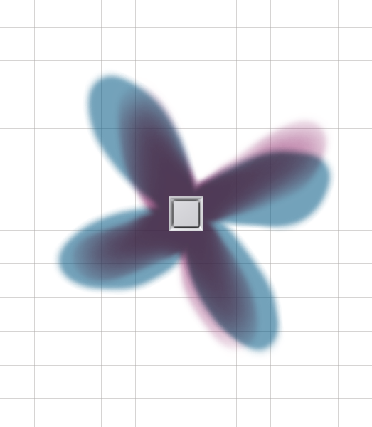
Figure 6: Perforated Diffuser
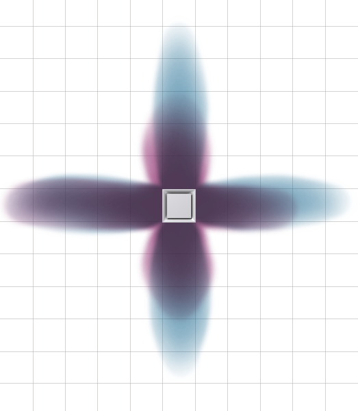
Figure 7: Directional Diffuser
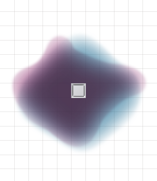
Figure 8: Square Plaque Diffuser
90-Degree Flexible Duct Connection
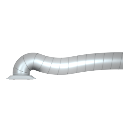
Figure 9: 90-Degree Flexible Duct Connection
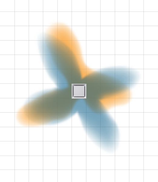
Figure 10: Perforated Diffuser
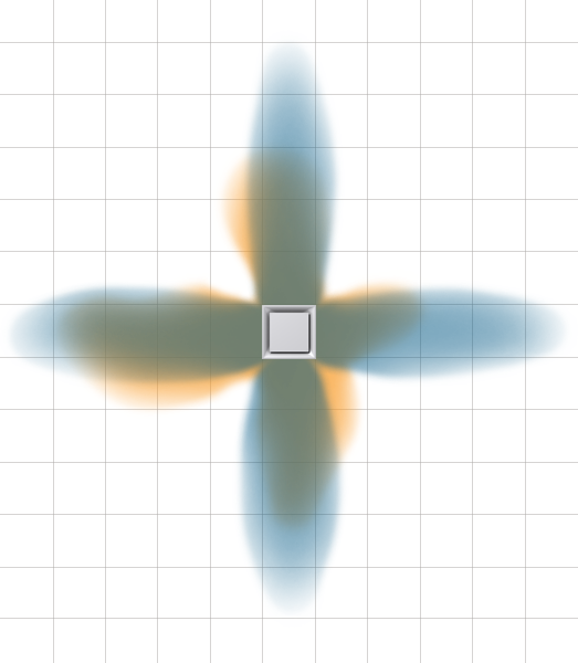
Figure 11: Directional Diffuser
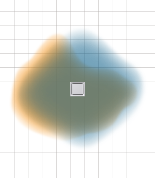
Figure 12: Square Plaque Diffuser
Radial Opposed Blade Damper
Figure 13: Radial Opposed Blade Damper
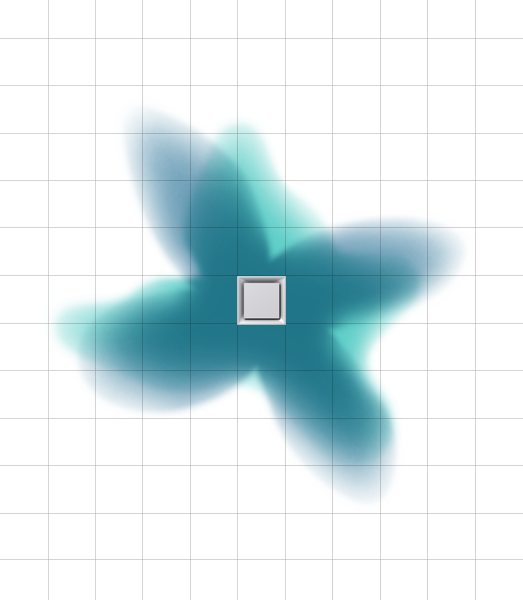
Figure 14: Perforated Diffuser
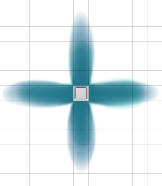
Figure 15: Directional Diffuser
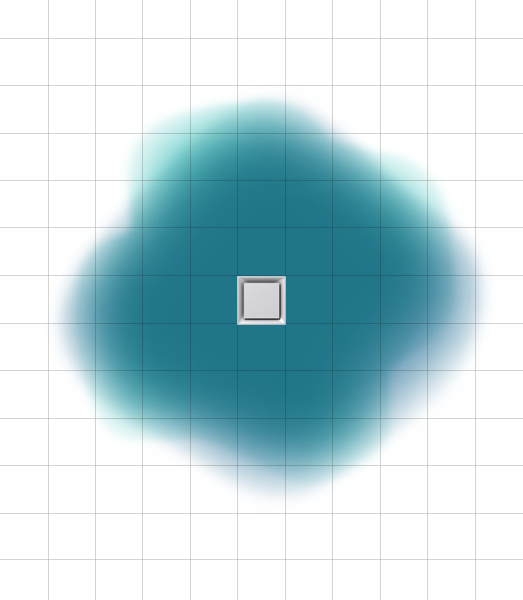
Figure 16: Square Plaque Diffuser
Butterfly Damper
Figure 17: Butterfly Damper

Figure 18: Perforated Diffuser
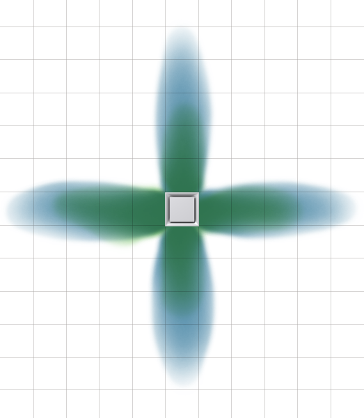
Figure 19: Directional Diffuser
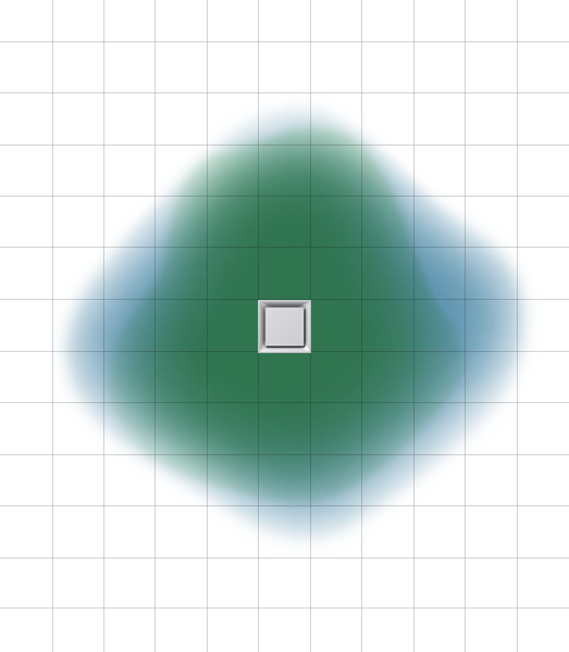
Figure 20: Square Plaque Diffuser
Radial Damper
Figure 21: Radial Damper
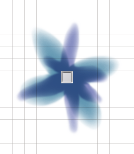
Figure 22: Perforated Diffuser
The diffuser retains its four-way pattern, but the addition of the radial damper shortens the throw and consequently increases the drop. Compared to the four previously discussed inlet conditions, the radial damper causes the most dramatic effect on air pattern of the square plaque diffuser, although still much less than with the other diffusers. Similar to earlier examples, the directional diffuser shown in Figure 23 sees a less drastic change in air pattern.
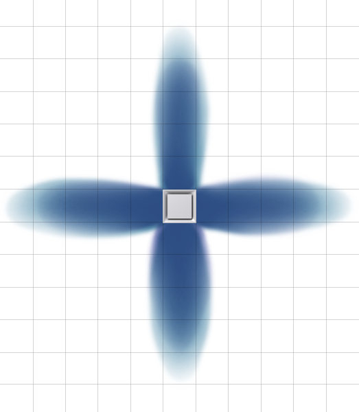
Figure 23: Directional Diffuser
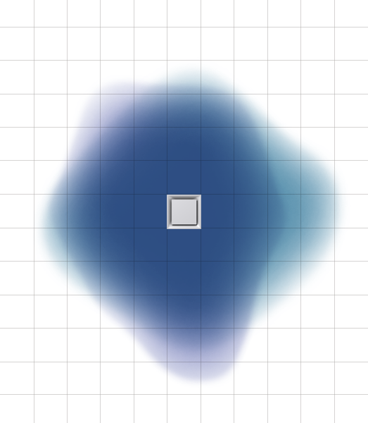
Figure 24: Square Plaque Diffuser
Conclusion


