Providing Supplemental Reheat to the Highest Standards of Safety
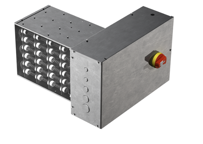
Electric coils are an HVAC accessory that in certain applications utilize electricity to reheat conditioned supply air for an occupied space. There are two types of electric coils provided on Price's terminals and fan coils: duct heaters and terminal unit heaters. Both achieve the same goal of providing supplemental reheat to the occupied space but differ in their construction and configuration.
The duct heater is designed to be a stand-alone heater and is certified to UL 1996, the standard for electric duct heaters. The electric coil mounted within Price’s Single Duct Terminal Unit (SDV) is also certified to UL 1996 as the coils have no integrated wiring connections to other electrical components and function as a stand-alone duct heater.
The terminal unit heater is designed to be built and integrated into fan-powered terminals and fan coils per UL 1995, which is the certification rating for units with heater subassemblies. All units produced by Price are UL certified, meaning the units are constructed to the highest electrical standards of safety.
 |
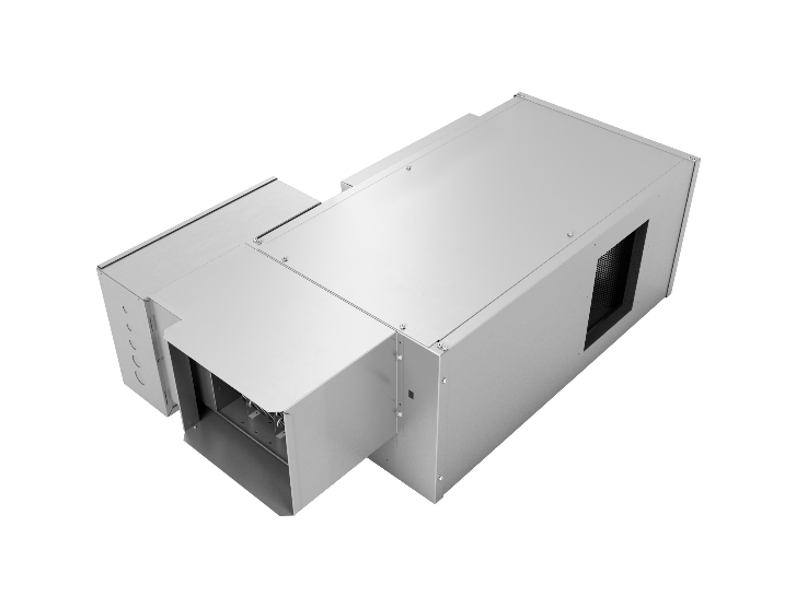 |
| A stand-alone electric duct heater (left) and a terminal unit heater (right) | |
The Price electric coils are equipped with 80/20 nickel-chromium elements that are strung in different orientations and lengths to accomplish the required heating capacity. There are multiple ways to control the output of the coils, including using contactors or a silicone control rectifier (SCR).
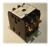
The simplest and most affordable way to control a heater, contactors are used to power the coils up to three equal stages or steps. Contactors are controlled by a 24 VAC signal that is used to close a high-voltage connection, allowing electricity to pass through and energize the electric coils. Coil elements are always powered at their maximum electrical potential. Multiple stages allow for fractional heat output from the coil. For example, a two-stage, 5 kW coil will have an output capacity of only 2.5 kW when one stage is energized. When both stages are energized, the output capacity will be 5 kW.
 |
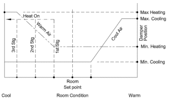 |
| A three-pole contactor (three stage) with a staged control sequence diagram | |
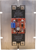
An SCR controller uses a different set of principles to vary the heat output of the element. The SCR can linearly modulate the heat output from 0% to 100% based on a 2–10 VDC signal, a 4–20 mA signal or a 24v PWM signal. This style of control works by energizing the coils at full power for short periods of time over a two-second duty cycle. This allows for incremental temperature changes, providing thermal comfort and energy efficiency improvements over contactors.
 |
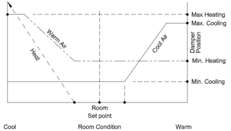 |
| An SCR controller with an analogue control sequence diagram | |
Safety is key when working with high-voltage electric coils. All Price electric coils come with a minimum of three safety features. In duct-mounted electric coils and single-duct electric coils, this includes the automatic reset, the manual reset and the airflow switch. In fan-powered electric units, this includes the automatic reset, the manual reset and the fan switch relay. These safety features are required per ETL/UL certification.
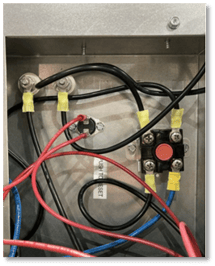
The automatic reset is a component that turns off the power to the coil elements once the reset reads a temperature exceeding 130°F. The unit will remain off until sufficient cooling occurs.
The manual reset is a component that trips if it measures a temperature exceeding 150°F. Once the manual reset is open, the only way to reenergize the coils is to manually push the button on the reset to allow current to pass through it again.
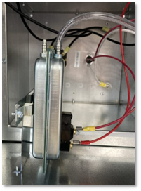
The airflow switch in a duct heater is a pressure switch that proves air is passing through the unit. If the airflow switch detects a difference between pressure in the unit and atmospheric pressure, the airflow switch closes and allows the coils to power on; when there is no difference in pressure, the airflow switch remains open, preventing the coils from turning on.
In fan-powered boxes, the fan switch relay is a component that is used to verify airflow prior to a signal continuing to the contactors or SCR. A fan signal from the unit controller will close the fan switch relay, in turn allowing power to continue to the rest of the electric coil assembly.
 |
 |
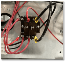 |
| Automatic and manual reset switches (left), an airflow switch (center) and a fan switch relay (right) | ||
For more information about how we use electric coils or about terminal units and fan coils, contact the Terminals team at airmovement@priceindustries.com.


